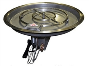
Rectangle, Bowl Pan Fire Pit Insert – Electronic Ignition
Rectangle, Bowl Pan Fire Pit Insert – Electronic Ignition
Model # / Description /BTU
24X12SS75HWI-H-LP H-Burner Fire Pit (LP)
24X12SS75HWI-H-NG H-Burner Fire Pit (Nat Gas)30X12SS100HWI-H-NG H-Burner Fire Pit (Nat Gas)
30X12SS100HWI-H-LP H-Burner Fire Pit (LP)
36X14SS125HWI-H-NG H-Burner Fire Pit (Nat Gas)
36X14SS125HWI-H-LP H-Burner Fire Pit (LP)
42X14SS150HWI-H-LP H-Burner Fire Pit (LP)
42X14SS150HWI-H-NG H-Burner Fire Pit (Nat Gas)
54X16SS200HWI-H-LP H-Burner Fire Pit (LP)
54X16SS200HWI-H-NG H-Burner Fire Pit (Nat Gas)
We advise that products be installed by professionals who are locally licensed by the authority having jurisdiction in gas piping.
WARNING:
Confirm this appliance is built for gas used – either natural gas (NG) or liquid propane (LP). Do not use a NG appliance with LP or an LP appliance with NG. Refer to the label on the appliance.
To prevent damage, unhook fire pit from gas supply for pressure leak tests. Fuel line sizing is the responsibility of the installer and must be able to supply the stated maximum BTU for the product.
Burn Testing- It is the responsibility of the qualified installer to test for gas leaks at all connections. When filling the pan with lava rock and/or decorative glass, the instructions in manufacturer's Section 5 must be followed.
Gas Plumbing Connections: Use only joint compound or tape that is resistant to all gases. Apply joint compound to all male pipe fittings only. DO NOT use on FLARED fittings. Be sure to tighten every joint securely. For systems with an extended or detached valve box the area in which the valve box is installed must conform with all installation requirements to include but not limited to location, construction, venting and local codes. Failure to do so may result in personal injury property damage or explosion.
Electronic Ignition fire pits come with a 13” x 13” sheet of insulation between pan and valve box to protect internal components from heat damage. This may need to be trimmed on smaller enclosures for proper fit. Please use insulation at all times.
WARRANTY REQUIREMENT:
For Electronic Ignition Models the Warranty is void if valve box is opened.
If need be, refer to manufacturer's website for important dimensional information for your fire pit.
Plan your project well in advance to comply with all instruction and codes and allow for access and serviceability of the product.
Perform all leak tests with leak detector or leak reactant.
Verify correct gas type and pressure.
Perform leak test on main gas supply. Repair leaks as necessary. Shut Off Gas Supply and Power to fire-pit. Connect fire-pit to main gas supply. If using flex line avoid sharp bends with flex line to prevent whistling. Turn on gas supply and perform leak test on all inlet connections. Repair as needed.
For electronic ignition models hook up proper 110VAC or 24VAC electrical power following all local codes. On electronic ignition models the 6’ power cord can be either tied into the main power supply for use with wall switch or plugged into remote receiver to use remotely.
Position fire pit safely with access to all gas connections for testing. Light fire pit. It may take several cycles to purge air from the lines.
For electronic ignition models apply proper 110VAC or 24 VAC.
Once fire pit is lit perform leak test on all gas connections. Repair as needed. Turn off fire pit and allow to cool.
Apply media as described in (Section 5). Turn on fire pit again and perform leak test with media correctly installed. If gas leak is detected verify correct media application and repair as needed. If trimmer valve is installed adjust flame to desired height. (Never alter the product configuration.) Set fire pit in properly constructed enclosure (Section 3). Verify operation and lighting. Review safety manual that accompanies product(s) and do not to change/ modify fire pit or media. Save manual for future use.


